_History
My Great Grandfather, Ellis Stillwell, from Alexandria, South Dakota, went to the Canal Zone in 1911, straight out of engineering school at the University of Wisconsin. He eventually went on to become engineering superintendent of the locks. His daughter, Jean Stillwell Crook, was born in the Canal Zone and married Bruce Crook Sr. who also worked in the Canal Zone and was there when my father was born. Recently, I had the honor of continuing the cross generational involvement with the Panama Canal and worked on the Third Set of Locks Expansion.
Education
Prior to my 20 years of structural and civil engineering design experience in the private sector I attended Santa Clara University from 1988-1994 and received a Bachelor of Science in Civil Engineering along with minors in Business and Spanish. While in college I worked for the Department of the Interior, Bureau of Land Management as a survey technician in Lake County, California and with my grandfather, a building contractor, in Ukiah, California. It was through those summer jobs in college where I learned that civil/structural engineering would be a better lifelong occupational fit for me than my original chosen field of accounting/business.
_
PROJECT EXPERIENCE
PROJECT EXPERIENCE

Seven C's Condos
Kill Devil Hills, NC, 2014
By Michelle Wagner on March 9, 2014
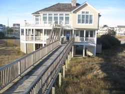
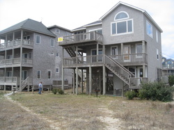
The rebuilding of the Seven C’s condominium complex on the Kill Devil Hills oceanfront is expected to begin in May, more than a year after the original 15-unit structure burned to the ground. A site plan for the new construction at milepost 7 was approved by the town’s Board of Commissioners Planning Board last night. The blaze that flattened the complex began during the early evening of Jan. 10, 2013 and burned for 12 hours before firefighters put out the flames. The cause was never determined. Jeff Shields of Seaside Management Inc., Seven C’s property management company, said he expects construction to take about nine months and added that the new building, designed by Cahoon & Kasten Architects in Nags Head, will be more attractive and include additional features. “Unfortunately it won’t be done by this summer, but we will have it ready to go by Thanksgiving,” he said, adding that the loss last winter was devastating for owners of units that were just over 1,000-square-feet apiece. The owners were comprised primarily of out-of-towners who used the homes as rental properties and vacation homes.
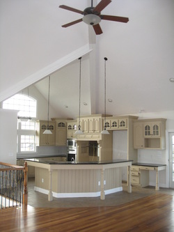
“The phone call I had to make to the president of the Seven C’s was one of the hardest calls I have ever had to make — to tell them that the building was a total loss,” he said. “Many of these people have more than one mortgage and are going two summer seasons without a home.” The old building, constructed in the early 1980s, was a boxy structure made up of modules, Shields said. The new building will be a stick frame and include more features such as towers and style consistent with old Outer Banks architecture. The rooflines have also been changed to make it more aesthetically pleasing, he added. “It is going to be a really attractive building,” he said. Each of the 15 two-bedroom units will remain just over 1,000 square feet. Shields said it was a challenge to fit design onto the property. The entire building will be a little more than 18,000 square feet and will include a swimming pool. The most noticeable difference, aside from the design, will be that the building will be moved significantly to the west. “It is going to be pushed considerably toward the beach road because of setback regulations,” Shields said. Also notable will be that while originally parking was to the west of the complex, now it will be underneath the building. There will be 30 parking spaces. According to Seaside Management’s webpage, the Seven C’s was named after the original seven developers, all members of the local Creech family. Many vacationers returned year after year to the Seven C’s during the summer months.

Ocean Sands Wastewater Treatment Plant Expansion
Corolla, NC, 2014
By Barrett Crook on July 7, 2014
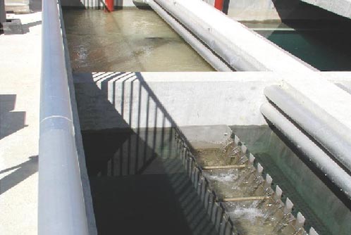
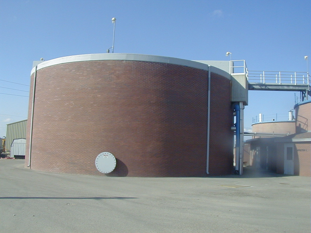
Kitty Hawk Engineering, PLLC, has teamed with Anlauf Engineering, PLLC, GET Solutions, Inc. and Michael Robinson, PE, PLS to design and permit a new 200,000 gpd WWTP for Currituck County in Corolla, NC. The project will consist of concrete influent channels, splitter boxes, headworks, primary clarifiers, flow equalization chambers, SAGB reactors, clearwells and solids holding tanks. The structures will be reinforced concrete constructed primarily above ground with metal access stairs and walkways. The construction of these items is all part of the first of four phases designed to dramatically increase the treatment capability of the Ocean Sands Wastewater Treatment Plant.
Tanger Outlet Center, Nags Head, NC 2013
Rear service road bridge inspection, front parking lot bridge inspection and main deck inspection.
Rear service road bridge inspection, front parking lot bridge inspection and main deck inspection.

Elevated Reservoir, Palestine, 2009
Palestinian Village Gets Its First Water Network March 15, 2011 ANERA
Water covers more than two-thirds of the earth’s surface but that doesn’t mean everyone has access to it. The 2,500 residents of Arrana had no water network and no access to a regular supply of potable water. Arrana, located just north of Jenin, is home to farmers who grow wheat and vegetables for a living. The only available water came from wells using tankers. But that didn’t ensure the water was safe to drink. “Our only option was to use water drawn from random wells, and because we didn’t know the source of the water, we couldn’t guarantee that it wasn’t contaminated by sewage or exposed to other unsanitary sources,” confesses Mr. Ghazi Abu Hananeh, head of Arrana village council. “We were all unhappy with the situation, especially since many residents were constantly complaining of illnesses. Local doctors said that their symptoms were related to water-borne diseases.” This reservoir, part of the newly built water network in the village of Arrana, holds enough water for 2,500 villagers. Mrs. Amina Mohammed (Um Abdallah), mother of six, tells us how inconvenient and hard life was before ANERA intervened. They were plagued by the constant fear that water would run out. Arrana’s families had only one option for getting water. They had to rent a tanker, travel to a well and draw the water, then travel back to their home and fill the water tank there. The local school also needed large amounts of water which had to be collected every three days. Not only was this process a burden on the villagers’ daily lives, but the high cost of water was also a huge financial drain. Um Abdallah explains, “We had to rent a tanker and buy water every two weeks. It used to cost us nearly 300 shekels [$82US] a month, and it was too much.” ANERA used $750,000 of USAID funding under the Emergency Water Sanitation and Other Infrastructure (EWAS II) Program to construct an elevated water reservoir, install a main line, a complete water distribution network, booster pumps and a chlorination unit to disinfect the water. The village council also collected $140,000 from local households and businesses to install house connections to the water network.
Mr. Ghazi says some families were no longer able to afford water. “Something had to be done. We needed help and so we contacted ANERA and, thank God, with USAID funding, they responded quickly.” “Now we can clean our home and ourselves as we please without having to worry about water shortages and cuts. We are also fortunate to be able to water our plants more often.”

Panama Canal Expansion
Panama, 2013
Submersible pump cages and pipe supports for the third set of locks were designed for the Panama Canal Expansion. The submersible pump cages facilitated the lowering of dewatering pumps down into the bottom of the canals in order to dewater them. The pipe supports were designed for extremely high thrust pressures and seismic loads.
Point Fortin Intake and Outfall Piping Systems, Trinidad, 2011
HDPE pipe diameter and pressure rating (DR) for the Point Fortin intake and outfall piping systems included an analysis of the pipe DR requirement based on three areas exposed to different loading conditions, the discharge of the intake pumps, the outfall in surf zone, the outfall beyond the surf zone, concrete anchor spacing and weight requirements for DR selected, hydraulics of intake and outfall HDPE submerged sections for selected DR, recommendations,
DR Pressure Rating.
|
Willamette River Water Treatment Plant
Wilsonville, Oregon, 2000 This was a large design build project and the design team completed the $41 million (total fees) project in less than 3 months. This project used an importance factor of 1.25 (essential facility) which was later upgraded to 1.50 after recommendations from a third party, value engineering committee. As a member of the design team and lead structural engineer the following tasks were accomplished:
The design and build contract was awarded to Montgomery Watson Harza in 2000, with a 28-month period for devising the scheme, acquiring the necessary permits and construction. The plant commenced operation in April 2002, providing 11,000m³/day at first, ahead of the full initial capacity of 57,000m³/day. The design permits a final phased expansion to 265,000m³/day to cope with long-term projected future needs. Currently, the city-wide demand varies seasonally between a summer peak of 22,000m³/day and 7,500m³/day in the winter. The overall scope of the project includes a high-service pump station, access roads and finished water pipeline, in addition to the design and construction of the raw water intake facilities and the treatment plant itself. After completion in 2002, the $43.8 million works received its first major award - the "Best of 2002" in the category of Outstanding Public Project for Oregon. WILLAMETTE RIVER WATER SUPPLY The city's original water supply came from a system of eight local wells. It was realized back in the 1990s that this would ultimately be insufficient for Wilsonville's fast-growing demand and studies were implemented to determine the best course of action to ensure long-term, sustainable water resource. Pilot tests conducted during this period using conventional treatment methods confirmed that even under "worst case" conditions, treated water from the Willamette River could consistently meet drinking water standards. However, until the issue was properly resolved, a moratorium was imposed on new development in the metropolitan area. When the state of Oregon decided to construct a new prison - the Coffee Creek Correctional Facility - in the city, the question of water supply gained additional interest and urgency and the City of Wilsonville decided upon the Willamette River WTP project in response. WATER TREATMENT PLANT Water is extracted from the Willamette River through an intake structure placed in mid-flow, above the river bottom and below the surface, to exclude both silt and floating material. Periodic air back-flushing is used to clean the intake screens of accumulating debris. The plant uses state-of-the-art disinfection and filtration techniques, coupled with the innovative Actiflo clarification process, which leads to greatly improved settling speeds within the small footprint of the facility. Enhanced sedimentation removes particulates which have passed through the intake screens using a combination of conventional coagulants to form the suspended materials into floc and the addition of very fine sand to increase its weight. As a result, settling occurs more quickly and more completely than under a conventional water treatment regime, which would require an area 15 to 30 times larger to achieve the same sedimentation effectiveness. The sand is subsequently reclaimed, cleaned, recycled and reused. The water is then ozonated. This serves a number of functions, including disinfection and the breakdown of organic chemicals, enhancing the removal of organic material by the filters. At the plant, liquid oxygen is used to generate the ozone for the treatment process, being evaporated into gaseous form and then converted on-site to ozone. This ozone is bubbled through the water during the treatment process, before being converted back to oxygen gas and released to the atmosphere. Subsequently, the flow enters a granular activated carbon filter, where any residual turbidity, pathogens or organic chemicals not already removed by the earlier treatment processes are removed, ahead of being polished in a sand filter. These filter layers are around 2m and 30cm thick, respectively. The fully treated water flows into an underground storage tank, where a small amount of chlorine is added to prevent bacterial contamination as the water is pumped through the distribution system pipes. The plant itself occupies a 10-acre site, of which half has been made into a nature park with a series of cascading ponds, rock walls and an open meadow which visitors are able to enjoy. The creation of this open space was made possible by the deliberate use of efficient building design, laying all of the treatment facilities out in a compact line along the eastern boundary of the site. The selection of the space-saving, high-rate ballasted sedimentation process was particularly important in enabling the overall design goals to be achieved, which ultimately led to the recent ASAL award. WTP PERFORMANCE The treatment facility is effectively over-designed, with current drinking water standards achievable without recourse to such extensive treatment. In addition, the treatment plant has also been designed with redundant systems for all these processes, to maximize continuity of supply and to facilitate expected future expansion. In 2003 - the most recent year for which figures are available - the plant easily exceeded the requirements established for potable water by the US Environmental Protection Agency. None of the regulated microbial contaminants (Coliform, Faecal Coliform, Giardia, Cryptosporidium) were detected. The water was free of volatile organic compounds (VOCs) and synthetic organic compounds (SOCs) and well within limits on other parameters including the increasingly important disinfection by-products (DBPs). |
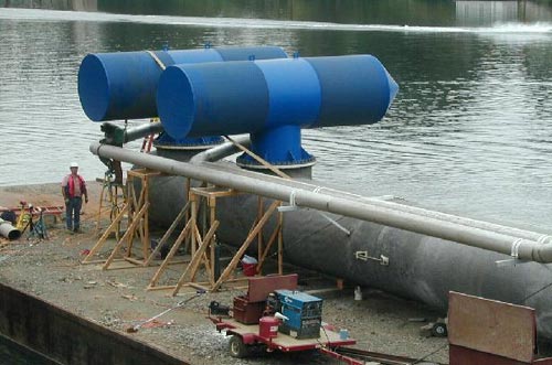
Intake screens awaiting positioning during the construction work. The plant takes raw water from the mid-flow of the Willamette River.
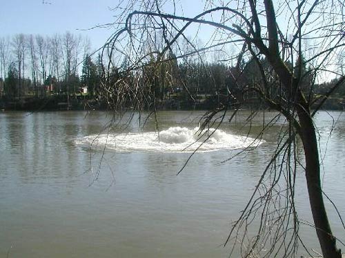
Periodic air back-flushing is used to clean the intake screens of accumulating debris.
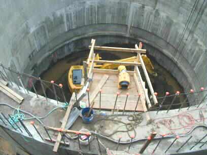
Excavation on the caisson in November 2000. The caisson had 4'-0" thick reinforced, concrete walls, a 4'-0" thick structural floor slab along with a tremie slab beneath the structural floor slab. Sections were built above grade and then sunk into place as the soil inside was excavated and removed. Extreme caution was exercised to avoid the caisson sinking on one side too rapidly causing a rollover/tilting issue.
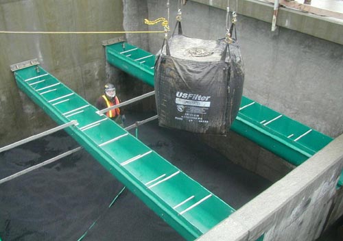
The filter during construction. It consists of a granular activated carbon filter and a polishing sand filter, 2m and 30cm thick respectively.
The finished filter in operation.
|
|
The plant's ozone machine generates the ozone required for disinfection, which is then bubbled through the water. Residual ozone is converted back to oxygen gas and released to the atmosphere.
Laying the water pipeline. The Williamette plant has a submerged water intake.
Award Winning Architectural Features
Included in the project scope is a 15 mgd plant that will service the residents of Wilsonville, a public park/landscape, an interpretive display, an 800 foot concrete and stone "garden wall" (the west wall of many of the plant buildings) that conceals the plant from the public park and from the neighbors. It also forms a backdrop for interpretive displays and for sheltered picnic areas. Also included is a 6,000 s.f. administration building which will house a laboratory, a conference room and support offices. Design: The "garden wall" runs north-south, bisecting the site into the secure water treatment plant on one side and a public park and ponds on the other. The wall is essentially a series of connected building elevations that express the public works functions beyond. The garden wall maintains a top of wall datum line that is constant. The wall stays level as the site drops to the river bank. At the south end, the raw water pump station pulls river water up to begin the process. Each wall segment denotes a particular purification process such as ozone generation, acti-flo (sedimentation), filtration, clear water storage and finally high pressure pumps that distribute water to the community. From the garden side, a path of interpretive panels and view window portals look into and explain the piping, pumps, filters and water of the operating functions of the facility. This path along the wall culminates in a river view lookout. A public meeting room attaches to this wall and sits in a pond. Two park shelters containing 30 - student long picnic tables also attach to the wall. The public park/landscape includes a water feature that consists of a series of ponds that continue through the length of the site. Storm water from the park side will empty into the different ponds. These ponds will enhance the local wildlife corridor along the western edge by providing natural eddies and emergent plants. The plants in the landscape are indigenous to the area and the surface treatment is mainly comprised of meadows with gravel pathways. |
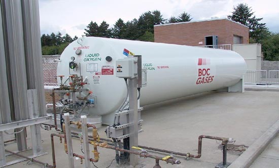
Liquid oxygen is used to generate the ozone; it is evaporated into gas and then converted on-site to ozone.
The sedimentation tanks; enhanced sedimentation removes particulates using a combination of conventional coagulants and the addition of very fine sand to increase floc weight.
The plant's clearwell (underground storage tank) where a small amount of chlorine is added to the treated water before it enters the distribution system.
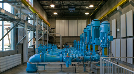
Pumps in the High Service Pump Station above the Clearwell.
|
Choir Room Remodel
Eastern Star Church of God in Christ
403 Factory Street
Elizabeth City, NC
Eastern Star Church of God in Christ
403 Factory Street
Elizabeth City, NC

Remodel
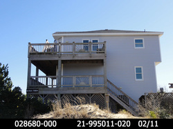
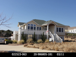
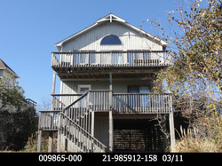
119 Ocean Blvd
Southern Shores, NC
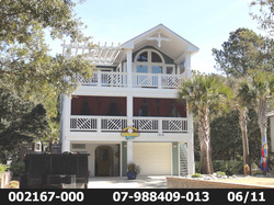
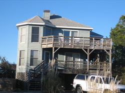
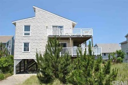
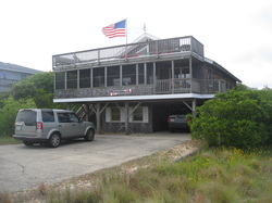
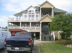
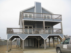
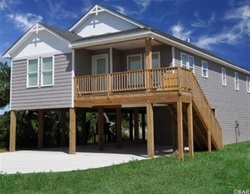
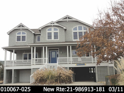
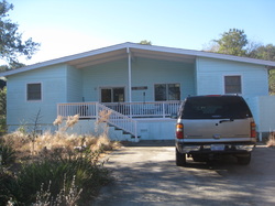
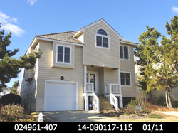
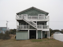
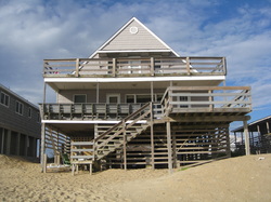
With a vibrant new exterior paint design, 119 Ocean Boulevard (Millis Cottage) is one of the most beautiful of the flat tops, enhanced by the artfully-landscaped grounds. . .this photo accompanies the recent article by Marimar McNaughton and was taken by Marie Walker.
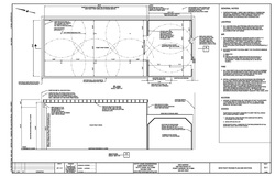
1600 sq-ft Pre-Engineered Metal Storage Building-Foundation Design
650 N. Bush St., Ukiah, CA
650 N. Bush St., Ukiah, CA
Oxidation Ditch/Carrousel Repair Recommendations
Zephyrhills, FL, 2008
On Monday, September 8th, 2008, a structural inspection of the Oxidation Ditch/Carrousel at the Zephyrhills Wastewater Treatment Plant in Zephyrhills, FL was conducted. A number of items on the structure that required immediate repair/maintenance were identified along with some items which only required monitoring. Items of concern included exposed and deteriorating rebar, spalled and delaminated concrete, diagonal cracking at the tops of walls, efflorescence, damaged expansion joint membranes, corrosion "conglomerates" on the inside face of walls, organic growth on the underside of the top covers at the North end, rock pockets at the South end of the divider wall, horizontal cracking on the top walkway and an abandoned pipe penetration on the inside of the North wall.
Combined Filter Effluent Flume Rehabilitation
WPB Water Treatment Plant, West Palm Beach, FL, 2011
At the request of West Palm Beach WTP Manager, Sam Heady, a limited structural evaluation of the Combined Filter Effluent (CFE) flume located at 1009 Banyan Blvd, West Palm Beach, Florida was conducted. This was in response to a request to evaluate the structure prior to work commencing on adjacent structures and to evaluate the condition of repairs made in 2009. In addition, The WTP experienced a "hydraulic event" on March 31, 2009 which resulted in surcharging of the Combined Filter Effluent (CFE) concrete flume and appurtenant structures. At the time of the event WTP staff noticed several active "blowouts" and subsequent sink holes in the soils adjacent to the CFE weir box, CFE chemical feed box and CFE flume. Subsequently, the City of West Palm Beach and US Water (operator of the plant) engaged Malcolm Pirnie and Structural Preservation Systems (SPS) to evaluate the structure, inspect the interior and conduct repairs. The repairs performed by SPS within the CFE flume included the sealing of various construction joints with hemp rope impregnated with hydrophilic epoxy grout and sealing of the overflow box opening with mortar grout. The opening was backed with a plywood form, several reinforcing rods doweled into the sides of the opening, and a Plexiglas cover placed on the interior wall of the CFE flume to protect the mortar during curing. The time for the work was limited to 4 hours due to limitations for stilling flows from the WTP. On April 3, 2009, WTP staff excavated the Southwest corner of the CFE chemical feed box down to the top of the overflow box, a depth of approximately 7 feet. The construction joint at that location was leaking heavily, approximately 1 gallon per minute. On April 6, 2009 the WTP CFE flow was stilled for 2 hours to allow for entry by WTP staff for inspection purposes. The water leveled was lowered to about 2.5 feet above the floor of the flume.
Observations included:
Heavy carbonate scaling within approximately 30 feet of the CFE weir
· The mortar-fill in the old overflow box was intact except for a small pencil-sized leak in the upper left hand corner.
Negligible water dripping from an overhead construction joint previously repaired by SPS
A blow-by in the corner of the concrete wall East of the CFE stop log guide tracks approx. 3 ft off the floor of the CFE weir box with approximately 25 gpm of flow into the flume which appeared to be coming through via a 1948 construction joint hidden behind a newer concrete pouR
A leak in the CFE weir box halfway along the West wall also at the assumed location of the 1948 construction joint
Based on these observations and a review of construction drawings from 1926 and 1948 it is surmised that the observed leakage coincided with construction joint locations and that these construction joints were likely compromised in a number of areas. It appeared that steel waterstops and asphaltic joint sealer were utilized for the construction joints and were failing. Recommendations were made at this time to eliminate the potential for cross-connection between the CFE flume and untreated water (groundwater and storm water). Repair recommendations included repairing the construction joints with hydrophilic epoxy joint sealant as opposed to structural epoxy because of the shorter curing time.
Locations which received this repair included:
The pencil-sized leak in the upper left-hand corner of the overflow box opening
A blow-by in the corner of the concrete wall, East of the CFE weir guide tracks, approximately 3 feet off the floor of the CFE weir box
The leak observed in the CFE weir box, mid-point along the West wall of the box
Digester and Control Building, West Boise, ID, 2006
The scope of design included a new digester control building, the demolition of select items, installation of new process equipment, and constructing new and/or making modifications to the following major facilities: Existing filtrate tank, new 1.2 million gallon concrete digester no. 3, existing digester control building pipe modifications, existing digester no. 1 and no. 2 pipe modifications, new odor control system, sitework improvements, yard piping, utilidors “A”, “B”, and “C”, new road, process instrumentation and control system, and power system including MCC and distribution system reroute, including support piping, plumbing, fabricated metal work, painting, instrumentation and controls, electrical, and sitework.
The scope of design included a new digester control building, the demolition of select items, installation of new process equipment, and constructing new and/or making modifications to the following major facilities: Existing filtrate tank, new 1.2 million gallon concrete digester no. 3, existing digester control building pipe modifications, existing digester no. 1 and no. 2 pipe modifications, new odor control system, sitework improvements, yard piping, utilidors “A”, “B”, and “C”, new road, process instrumentation and control system, and power system including MCC and distribution system reroute, including support piping, plumbing, fabricated metal work, painting, instrumentation and controls, electrical, and sitework.
Phase 3a, Wastewater Treatment Plant Improvements, Caldwell, ID, 2004
The project consisted of a new CMU (above grade) and reinforced, cast-in-place, concrete (below grade) headworks facility, a reinforced concrete raw sewage pump station, a reinforced concrete magnetic flow meter vault, a reinforced concrete splitter box, a CMU shop building, circular, a reinforced concrete digester and a CMU digester control building.
The project consisted of a new CMU (above grade) and reinforced, cast-in-place, concrete (below grade) headworks facility, a reinforced concrete raw sewage pump station, a reinforced concrete magnetic flow meter vault, a reinforced concrete splitter box, a CMU shop building, circular, a reinforced concrete digester and a CMU digester control building.

Indiana Reservoir and Pump Station, Caldwell, ID, 2004
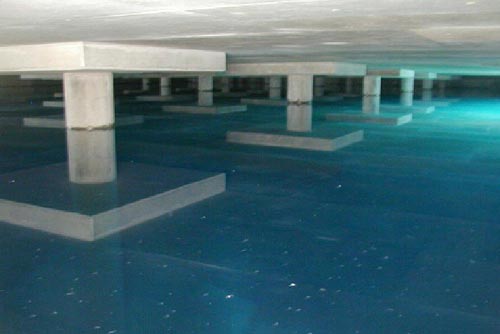
This design included a new 119' inside diameter, circular, concrete, pre-stressed/post-tensioned concrete tank with 25' tall, 1'-0" thick core walls, (16)-1'-6" circular concrete columns, 7-1/2" thick floor slab and an 8-1/2" thick roof slab. In addition, an 1800 sq-ft CMU pump station accompanied the reservoir.
This design included a new 119' inside diameter, circular, concrete, pre-stressed/post-tensioned concrete tank with 25' tall, 1'-0" thick core walls, (16)-1'-6" circular concrete columns, 7-1/2" thick floor slab and an 8-1/2" thick roof slab. In addition, an 1800 sq-ft CMU pump station accompanied the reservoir.

Aeration Basins and Primary Clarifier No. 3, Caldwell, ID, 2007
As part of the 2007 Phase 4 Caldwell Wastewater Treatment Plant Improvements a new Aeration Basin (with provisions for future expansion) and Final Clarifier No. 3 were designed. The Aeration Basin measured over 200' long, 38' wide and 25' tall with the Final Clarifier No. 3 measuring 110' inside diameter, 1' wall thickness and 17'-8" tall walls.
As part of the 2007 Phase 4 Caldwell Wastewater Treatment Plant Improvements a new Aeration Basin (with provisions for future expansion) and Final Clarifier No. 3 were designed. The Aeration Basin measured over 200' long, 38' wide and 25' tall with the Final Clarifier No. 3 measuring 110' inside diameter, 1' wall thickness and 17'-8" tall walls.

Grizzly 3MG Reservoir, West Jordan, UT, 2013
After designing the first pre-stressed/post-tensioned concrete tank and pump station for the City of West Jordan, Utah in 2000 the City requested another tank adjacent to the existing one. The second, nearly identical, pre-stressed/post-tensioned concrete tank for the City of West Jordan had nearly identical parameters, inside diameter of 184', core wall thickness of 1', circular wall height of 21' with 44 interior, 1'-8" diameter columns, 6" thick floor slab and an 8-1/2" thick roof slab.
After designing the first pre-stressed/post-tensioned concrete tank and pump station for the City of West Jordan, Utah in 2000 the City requested another tank adjacent to the existing one. The second, nearly identical, pre-stressed/post-tensioned concrete tank for the City of West Jordan had nearly identical parameters, inside diameter of 184', core wall thickness of 1', circular wall height of 21' with 44 interior, 1'-8" diameter columns, 6" thick floor slab and an 8-1/2" thick roof slab.

Central Treatment Plant Upgrade and Expansion Phase III
Tacoma, WA, 2005
The Central Wastewater Treatment Plant features one of the most technologically advanced treatment processes in the country. It serves Tacoma and about 20,000 customers in Fife, Fircrest and unincorporated Pierce County. Every bit of the biosolids material processed at the plant is recycled and turned into TAGRO gardening products - Mix and Potting Soil. These award-winning soil products will help your garden grow. The design-build plant upgrade included an expansion and enhancement of the plant's screening capabilities, expanded influent pumping capability, expanded and enhanced grit removal capability, expanded conveyance in various areas of the plan, flow splitting capability and enhanced flow routing in various areas of the plant, peak wet weather flow treatment, expanded effluent pumping capability, new plant-wide disinfection system that does not utilize chlorine gas, new and upgraded instrumentation and control capabilities, upgraded operations and control center, electrical distribution system upgrades, upgraded plant power supply, digester system heat exchanger and related system upgrades, new and expanded plant-wide boiler heating system, upgraded protected water system, yard waste/spray water system, expanded TAGRO processing facilities, plant maintenance building expansion and remodel, new scale facility, new septage receiving facility, new solids receiving facility, improved yard lighting and an interpretive center.

Santa Clara Valley Water District
Water Quality Test Lab
San Jose, CA, 2006
The water in our groundwater basin, our 10 reservoirs and in the creeks is a precious resource. The water district manages this resource to ensure that we will always have a reliable supply of healthy, clean drinking water. In 2008, the water district opened a new $17.5 million “state-of-the-art” water quality laboratory to meet increasing needs for water sampling and ever more rigorous testing. It replaced a lab which was built in 1968 when the water district tested 1,000 samples annually. Today, the water district tests approximately 140,000 samples a year. Both the treated water and “raw” imported water require constant monitoring to assure their safety. Many of those tests are in response to new water-quality regulations for “emerging” contaminants, such as cryptosporidium. The water district produces monthly water quality report showing the quality of untreated source water received at each of the district's three water treatment plants, and the treated water which the district delivers to water retailers in Santa Clara Valley.
- Because of the importance of our groundwater basin, the water district monitors groundwater quality through sampling water from a number of deep wells located throughout the county.
- Urban runoff contributes to our water quality. The water district participates in the Santa Clara Valley Urban Runoff Pollution Prevention Program to help prevent it.
- The Silicon Valley Pollution Prevention Center is another partner with the district in the effort to educate and encourage county residents to prevent pollution from reaching our creeks and rivers.
- The Leaking Underground Storage Tank Oversight Program was transferred to the Santa Clara County Department of Environmental Health July 1, 2004. The county maintains the electronic case files. For current information and to view former and current fuel leak case data please click here. Solvent and toxic release cases are overseen by various regulatory agencies. For more information click here.
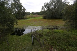
Blue Sink Pumping Station, Tampa, FL, 2013
Blue Sink Diversion: A pump station and pipeline are necessary to divert 3.1 cfs from Blue Sink to the base of the Hillsborough River Dam. The City has completed the design of the pipeline in the public right-of-way less any required pressure sustaining valves and SCADA monitoring points. The Consultant will design and permit the pump station and on-site piping.
Tampa will tap Blue Sink to boost river flow
By Kevin Wiatrowski | Tribune Staff
Published: December 28, 2013 | Updated: December 28, 2013 at 12:01 PM TAMPA — Tampa won approval this month for another project intended to protect the health of the Hillsborough River at times of drought. The Southwest Florida Water Management District gave a green light last week to a plan to pump up to 2 million gallons of water a day from Blue Sink, a natural pool just west of the point where Fowler Avenue meets Florida Avenue. The plan calls for running water lines from the sink to the foot of the city’s dam between Rowlett Park and Rogers Park in East Tampa. The dam, first built by ranchers a century ago, holds back the Hillsborough River to provide drinking water. The modern dam was built in the 1940s. Most days, it allows enough fresh water past to push back against the slug of salt water that moves up from Tampa Bay on each high tide. The fresh and brackish water below the dam makes the river an important breeding ground for fish and other sea creatures. That changes during droughts, when the freshwater flow slows to a trickle or stops entirely and salt water pushes farther up river. Years of lawsuits and arguing over the health of the river helped produce a calculation known as the river’s minimum flow level. That’s nearly 11 million gallons a day from July to March and 13 million gallons a day from March to June. Mayor Bob Buckhorn opened the first of four planned freshwater reserves last year when he flipped the switch on a new pump house at Sulphur Springs in North Tampa. That system can add nearly 10 million gallons of freshwater a day to the river during drought years. If the river needs more help, the city plans to tap Blue Sink, the Tampa Bay Bypass Canal and, eventually, Morris Bridge Sink to the north — in that order. “The intent is to make sure the health of the lower Hillsborough River is sustainable,” Buckhorn said this week. The city and Swiftmud are splitting the cost of the $11 million Blue Sink project. The idea of the city pumping millions of gallons of water from Blue Sink has the sink’s neighbors in the North Forest Hills area fearing for their wells. There are about 800 wells within a mile of the sink and Ewanowski Spring, which feeds it. “We’re concerned about lake levels and possible sinkhole development,” North Forest Hills resident Jim Wilson told the Swiftmud board. “We’re just concerned about what might happen.” Brad Baird, the city’s water department director, said the well owners have nothing to worry about. The city won’t pump from the sink year-round, Baird said. Some years, it may not need to draw from the sink at all. “During wet years, we may not need to use Blue Sink at all,” Baird said this week. “One very dry year or a drought, we’ll probably need to use Blue Sink more than half the year.” A 1996 study of Blue Sink and the surrounding land showed that pumping the sink at the level the city plans would drop lake levels by a foot or less. Barbara Ewanowski, who owns the spring that feeds Blue Sink, welcomes the pumping. The channel connecting the spring and the sink has been plugged by debris, causing the spring to back up and kill dozens of live oak trees on Ewanowski property, she said. Pumping water from the sink will restore more of the natural flow from the spring and bring her property some relief, she told the Swiftmud board. kwiatrowski@tampatrib.com
Lucas and North Regional Wastewater Treatment Plant Modifications
Shreveport, LA, 2013
Shreveport, LA, 2013
Modifications to the North Regional Wastewater Treatment Plan involved the design of a shade canopy over the UV structure and replacement of sludge presses and chemical feed equipment. Modifications to the Lucas Wastewater Treatment Plant also involved the design of a shade canopy over the UV structure along with the replacement of piping, valves and pumps in the pipe gallery tunnel, the replacement of digester blowers, controls and electrical equipment and replacement of the digester pump station building.

Venice Gardens Water Treatment Plant Expansion, Sarasota County, FL, 2012
The purpose of the Venice Gardens Water Reclamation Facility Expansion Project is to increase the capacity of the plant from 2.0 million gallons per day to 3.0 million gallons per day and to improve operations by adding a new head works, anoxic mixers and recycle pumps, return sludge pumps and a new blower. The construction contract for this project was approved by the Sarasota County Commission on Feb. 19, 2014. The Notice to Proceed was issued to the contractor, TLC Diversified on April 10, 2014 with completion expected in Winter 2015. Construction has begun on site.
The purpose of the Venice Gardens Water Reclamation Facility Expansion Project is to increase the capacity of the plant from 2.0 million gallons per day to 3.0 million gallons per day and to improve operations by adding a new head works, anoxic mixers and recycle pumps, return sludge pumps and a new blower. The construction contract for this project was approved by the Sarasota County Commission on Feb. 19, 2014. The Notice to Proceed was issued to the contractor, TLC Diversified on April 10, 2014 with completion expected in Winter 2015. Construction has begun on site.

Big Island Water Works
Chemical Improvements
City of Sandusky, OH, 2009
The main building of the Big Island Water Works or BIWW was a public works project built in 1940 that was later doubled in size in 1956 and was further improved upon in the 1970s. Another set of improvements, the Chemical Improvements Program, was implemented in 2009. The City Commission declared the necessity for the City to proceed with the Big Island Water Works (BIWW) Chemical Improvement Project which involved six (6) tasks including Chemical System, Lagoon Effluent Pumping System, Pre-Sedimentation Tank Improvements, Access Roadway and Parking, Sluice Gate Replacement and Security.

Phase III, Water Treatment Plant Expansion, Roseville, CA, 2004
The 2004 Expansion of the City of Roseville's Water Treatment Plant included additional flocculation-sedimentation and filter basins. The flocculation-sedimentation basins are in excess of 350' long, 56' wide and 20' tall. The filters basins are each 48' long, 12' wide and 15' tall. Both are reinforced concrete and were added to (physically connected) existing flocculation-sedimentation and filter structures which were originally built with future expansion in mind.
The 2004 Expansion of the City of Roseville's Water Treatment Plant included additional flocculation-sedimentation and filter basins. The flocculation-sedimentation basins are in excess of 350' long, 56' wide and 20' tall. The filters basins are each 48' long, 12' wide and 15' tall. Both are reinforced concrete and were added to (physically connected) existing flocculation-sedimentation and filter structures which were originally built with future expansion in mind.

Canal Improvements
Pinellas Park, FL, 2006
The soldier pile style retaining wall was used consisting of H-piles and precast concrete lagging to stabilize canal walls in Pinellas Park, FL. H Piles were spaced at 15' oc with precast concrete lagging spanning between them. To reduce the potential for excessive vibrations to nearby structures and their occupants, pre-drilling the top 10-15' of the pile hole and driving the piles to their remaining required depth was done. In addition, pre-drilling was done in order to minimize pile movement prior to lagging installation as the City had a negative experience with "shifting" piles resulting in the purchase of costly custom lagging of varying lengths.
To reduce the potential for pile movement, features such as extended pile depths and/or a lean concrete jetted in around the upper portion of the pile where the pre-drilling occurred were considered for further pile stiffening and alignment prior to lagging installation.

Patterson Irrigation District
Fish Screen Intake Project
Patterson, CA, 2009
Patterson Irrigation District provides irrigation water to nearly 13,500 acres of farmland and ranches in the San Joaquin Valley. Patterson Irrigation District’s 195 cubic feet per second diversion on the San Joaquin River has served as the district’s primary source of water for over 100 years. The San Joaquin River is a critical migration route for Chinook salmon and Central Valley steelhead which migrate to the ocean as young fish and then return in subsequent years as adults. The new Patterson Irrigation District Fish Screen and Intake Facility prevents entrainment of these at-risk native fish species by replacing their existing unscreened diversion with a state-of-the-art fish screen and intake facility which meets or exceeds federal and state screening criteria.

GE Motors Plant
Murfressboro, TN, 2009
A limited structural evaluation of the former GE Motors Facility located at 2150 Northwest Broad Street in Murfreesboro, Tennessee (Facility) was performed. The evaluation was conducted in response to tornado damage suffered at the Facility and included a review of structural drawings for the Facility and a Facility walk-through to evaluate building/structure conditions for short-term safety conditions and to evaluate long term re-use options for the Facility. Based on results of the limited evaluation, it appeared that the building did not pose an imminent risk of structural failure. However, it was recommended that a structural steel engineer review welds associated with the roof decking in an approximate 4,000 sq ft area in the northwest corner of the high bay. This was the area where the roofing material had been completely removed from the high bay area. It was also recommended that the air handler openings on the roof be sealed in order to reduce the potential failure mechanisms to the building of an open “building envelope”. This is a critical location because higher winds speeds are more likely at higher elevations and could subsequently lead to a domino style failure of the structure starting with the roof diaphragm.

North Shore Terminal Reservoir
Central Utah Water Conservation District, 2013
The North Shore Terminal Reservoir is a rectangular structure, formed from cast-in-place reinforced concrete with a hopper bottom shape to optimize construction costs per volume of stored water. Construction is to be in multiple phases to suit growth in demand and storage requirements. Adjacent cells are to be added in subsequent phases and shall utilize shared walls. Separate inlet and outlet piping shall be provided to encourage circulation through the reservoir. CUWCD personnel were provided access with a stairway through a large hatch. Additional equipment hatches were provided based on operational needs, and in conformance with IBC egress requirements.
Vent structures were combined with access hatches to limit reservoir cover penetrations. The Terminal Reservoir was designed with an overflow weir box. The Terminal Reservoir us a combined outlet and drain sump. Seismic actuation controls on inlet/outlet pipes were provided to retain emergency storage, but will always allow for immediate availability of flow for fire suppression and to meet customer demands. Closing times for inlet and outlet valves are at least the minimum required based on hydraulic transient analysis. Underdrains and perimeter drains were provided and metered to detect changes in leakage rates. A standpipe was provided on the site for the 30-inch vent from the North Shore Aqueduct (NSA). The design life of 50 years for concrete reservoir and buried pipelines (100 years of useful life is likely) was provided.
Phased construction of the NSTR will leverage staggered capital investment with future increases in customer demands. Near-term demands do not justify the expense of constructing the entire reservoir at one time, yet a minimum of 5 million gallons (MG) is required to be on-line by 2014. Each
phase of construction will add another cell to the reservoir, until the ultimate capacity of 40 MG is constructed. The following baseline schedule of phased construction (Phasing Schedule Alternative 1) has been proposed by the District with 10 MG of additional storage constructed at each stage:
• The first 10MG would be built in 2013,
• second in 2017 (total 20 MG)
• third in 2020 (total 30 MG)
• fourth in 2029 (total 40 MG)
Headworks, Eagle Sewer District, Eagle, ID, 2009
A new Headworks facility was built at the Eagle Sewer District (ESD) WWTP to replace the existing Headworks which was near its capacity and at the end of its useful life. Initially, raw wastewater will be pumped from the existing Headworks vicinity to the new Headworks and be gravity fed back to the existing lagoons for treatment. The new Headworks allowed gravity flow to the future ESD WWTP, to be constructed north of the existing lagoons some time in the future. The new Headworks consists of a raw sewage pump station, coarse screening, screenings washer/compactors, grit removal, conveyance for screenings and grit, influent and effluent piping, and an odor control system. The new Headworks was designed to meet the current WWTP capacity rating of 3 mgd (average daily flow). The new headworks was designed to accommodate peak hourly flow conditions which corresponds to a design peak hourly flow of 7.5 mgd, with provision to expand to 14.25 mgd ultimate peak hourly flow.
A new Headworks facility was built at the Eagle Sewer District (ESD) WWTP to replace the existing Headworks which was near its capacity and at the end of its useful life. Initially, raw wastewater will be pumped from the existing Headworks vicinity to the new Headworks and be gravity fed back to the existing lagoons for treatment. The new Headworks allowed gravity flow to the future ESD WWTP, to be constructed north of the existing lagoons some time in the future. The new Headworks consists of a raw sewage pump station, coarse screening, screenings washer/compactors, grit removal, conveyance for screenings and grit, influent and effluent piping, and an odor control system. The new Headworks was designed to meet the current WWTP capacity rating of 3 mgd (average daily flow). The new headworks was designed to accommodate peak hourly flow conditions which corresponds to a design peak hourly flow of 7.5 mgd, with provision to expand to 14.25 mgd ultimate peak hourly flow.

Final Clarifier No. 3, Nampa, ID, 2006
The 120 feet diameter (inside face wall diameter), 15 feet tall (concrete wall height), circular, reinforced concrete tank for the City of Nampa's Wastewater Treatement Plant was designed in 2006. The plant treats in excess of 3,600 million gallons/year; with a population equivalent of 250,000 with industry loadings. The Nampa Wastewater Treatment Plant removes 99% of BOD (Biological Oxygen Demand), 96% of TSS (Total Suspended Solids) and 99.6% of NH3-N (Ammonia). Wastewater flows by gravity to the Plant Headworks where it is lifted by the Raw Sewage Pumps. Then Step screens remove sticks and rags from the raw sewage flow. Grit basins remove inorganic grit and snail shells. Rag and grit removal reduces possible plugging problems and prevents excess, while also preventing excessive pump wear. From the grit basins, the flow is split through three flow meters which measure the raw sewage flow.
The 120 feet diameter (inside face wall diameter), 15 feet tall (concrete wall height), circular, reinforced concrete tank for the City of Nampa's Wastewater Treatement Plant was designed in 2006. The plant treats in excess of 3,600 million gallons/year; with a population equivalent of 250,000 with industry loadings. The Nampa Wastewater Treatment Plant removes 99% of BOD (Biological Oxygen Demand), 96% of TSS (Total Suspended Solids) and 99.6% of NH3-N (Ammonia). Wastewater flows by gravity to the Plant Headworks where it is lifted by the Raw Sewage Pumps. Then Step screens remove sticks and rags from the raw sewage flow. Grit basins remove inorganic grit and snail shells. Rag and grit removal reduces possible plugging problems and prevents excess, while also preventing excessive pump wear. From the grit basins, the flow is split through three flow meters which measure the raw sewage flow.

Final Clarifier No. 1 & 2 Rehabilitation
Nampa, ID, 2007
Final Clarifiers 1 & 2 at the Nampa Wastewater Treatment Plant were rehabilitated in 2007 with a new concrete grout topping slab and effluent launder. The plant treats in excess of 3,600 million gallons/year; with a population equivalent of 250,000 with industry loadings. The Nampa Wastewater Treatment Plant removes 99% of BOD (Biological Oxygen Demand), 96% of TSS (Total Suspended Solids) and 99.6% of NH3-N (Ammonia). Wastewater flows by gravity to the Plant Headworks where it is lifted by the Raw Sewage Pumps. Then Step screens remove sticks and rags from the raw sewage flow. Grit basins remove inorganic grit and snail shells. Rag and grit removal reduces possible plugging problems and prevents excess, while also preventing excessive pump wear. From the grit basins, the flow is split through three flow meters which measure the raw sewage flow.

Raw Water Pump Station, Augusta, GA, 2003
The Augusta Utilities Department currently provides water and sewer to a service area of 230 square miles and a population of over 160,000. Our distribution system consists of approximately 1,200 miles of water mains. Treatment of surface water occurs at the Highland Avenue surface water treatment plant (filter plant). The Filtration Plant with a design capacity of 60 MGD, provides the majority of the water supply. Average daily plant flows are approximately 24 MGD. Raw water for this plant is withdrawn from the Savannah River. The Raw Water Pumping Station, located off Riverwatch Parkway, utilizes the water from the Augusta Canal to hydro-mechanically power the pumps which pump the water from the Savannah River to the Highland Avenue filter plant. This station has been in operation since the late 1800s. Two ground water plants, Plants No. 1 and No. 2, have design capacities of approximately 10 MGD each. Ten wells provide raw water to Plant No. 2 and 14 wells provide raw water to Plant No. 1. There are a total of 28 ground water wells in operation. All wells withdraw water from the same aquifer. Average daily flows from ground water is approximately 15 MG. The Highland Avenue Filtration Plant is a conventional surface water treatment plant. Raw water is collected from the Savannah River via the canal and stored in two reservoirs located adjacent to the plant. Raw water is treated with lime, fluoride, chlorine, and/or corrosion control chemicals to ensure the water is safe for drinking.
The Augusta Utilities Department currently provides water and sewer to a service area of 230 square miles and a population of over 160,000. Our distribution system consists of approximately 1,200 miles of water mains. Treatment of surface water occurs at the Highland Avenue surface water treatment plant (filter plant). The Filtration Plant with a design capacity of 60 MGD, provides the majority of the water supply. Average daily plant flows are approximately 24 MGD. Raw water for this plant is withdrawn from the Savannah River. The Raw Water Pumping Station, located off Riverwatch Parkway, utilizes the water from the Augusta Canal to hydro-mechanically power the pumps which pump the water from the Savannah River to the Highland Avenue filter plant. This station has been in operation since the late 1800s. Two ground water plants, Plants No. 1 and No. 2, have design capacities of approximately 10 MGD each. Ten wells provide raw water to Plant No. 2 and 14 wells provide raw water to Plant No. 1. There are a total of 28 ground water wells in operation. All wells withdraw water from the same aquifer. Average daily flows from ground water is approximately 15 MG. The Highland Avenue Filtration Plant is a conventional surface water treatment plant. Raw water is collected from the Savannah River via the canal and stored in two reservoirs located adjacent to the plant. Raw water is treated with lime, fluoride, chlorine, and/or corrosion control chemicals to ensure the water is safe for drinking.

Filters, Surface Water Treatment Facility, Fresno, CA, 2001
While groundwater has traditionally been the sole source of water for Fresno, the Surface Water Treatment Facility (SWTF) now supplements our system with water delivered directly from the Sierra Nevada Mountains to the facility for treatment. The SWTF supplies thousands of homes in Northeast Fresno – more than 20 million gallons of water per day. During the peak demand summer season the facility supplies approximately 15% of Fresno's potable water. During the low demand winter periods the facility supplies more than 30% of the community's supply. A second surface water treatment facility is planned in southeast Fresno to meet demands anticipated by the redirection of growth suggested in the 2025 General Plan.
The SWTF utilizes a three-step treatment process: clarification, filtration and disinfection. “ACTIFLO®” is a patented term for a unique clarification process, which involves treatment additives plus microsand being injected into the water and rapidly mixed together to form a “ballasted floc.” This process removes suspended material and bacteria that may be living within those particles. The process repeats itself in a series of basins as the growing floc settles at the bottom. The cleaner water travels upward through a honeycomb-like set of tubing and is finally sent on to the ozone contact basin. This entire process is commonly called coagulation, flocculation, and sedimentation. While it could take nature several years to achieve this clarity of water, this entire process takes about 15 minutes.
The ozone contact basin is where both ozone disinfection and oxidation occur. Water coming from the ACTIFLO® process is injected with thousands of tiny ozone bubbles. A powerful oxidant, ozone destroys many types of microorganisms; color, taste and odor compounds; and some man-made organic compounds. Once the ozone has effectively done its job (within about 10 minutes), it rapidly dissipates. By the time the water leaves this basin, it is ozone-free and travels on to the granular activated carbon filters for additional purification.

Eastridge 16 MG Reservoir
Fairfield, CA
The Eastridge Reservoir is a 16 million gallon (MG) buried, reinforced concrete tank serving pressure zone 1. The reservoir was constructed in 2005 as a regular square shape divided into three cells (Cell 1, Cell 2 and Cell 3). Cell 1 has a capacity of 4 MG; Cell 2 also has a capacity of 4 MG while Cell 3 is the largest with a capacity of approximately 8 MG. All three cells are interconnected with transfer valves.

SBR's (Sequencing Batch Reactors)
Calera Creek Water Recycling Plant
Pacifica, CA
The Calera Creek Water Recycling Plant can treat 4 million gallons of sewage per day (up to 20 MGD during storm events). The sequencing batch reactors are innovative, in that they combine the basins for aeration and clarification, which are separate at most older plants.
This project helped pioneer the use of ultraviolet disinfection for wastewater effluent in California. UV allows release of recycled water into wetlands because residual chlorine was not allowed in the permitting process. This technology was developed by Trojan Technologies and tested by the City of Pacifica and UC Davis.
This plant is one of the first fully automated plants in the San Francisco Bay Area designed for nutrient removal. This is also one of the first plants using ATAD technology (autothermal thermophilic aerobic digesters) for the generation of Class A sludge in California.
Two diesel-powered generators maintain plant electricity in the event of a power outage. To minimize visual impact, the entire facility except for the filters and control building are buried in a hillside covered with native plants. The odor control scrubbers pull air from all process areas to neutralize odor-causing gases.
The plant has the first successfully restored wetlands using the Hydro Geomorphic model. This model for wetlands was developed for this project and is now the standard used by many resource agencies (including the Environmental Protection Agency and Regional Water Quality Control Board) for wetlands restoration design and monitoring. Thirty acres of wetlands, riparian vegetation and coastal scrub were restored in the process.
Pacifica’s wastewater flows by gravity to the Sharp Park and Linda Mar pump stations where it is screened to remove inorganic objects, then pumped to the Calera Creek Water Recycling Plant. The first stage of treatment at the plant is a vortex chamber that separates grit from the sewage.
Second, the influent goes to the SBR (sequencing batch reactors) basins, a combination of primary and secondary treatment and nutrient removal. Here, micro-organisms feed on the organic matter. Air is injected to assist the organisms and to mix the contents. After the organisms consume the sewage and solids, the remaining particles are allowed to settle to the bottom in the form of sludge.
Some of the sludge is left in the reactor basins because it contains the organisms that will multiply to feed on new sewage when it arrives. The rest of the sludge is pumped to a biosolids holding tank. The sludge is then thickened and pumped into the digesters. In the digesters, the ATAD organisms live at a high temperature (135 degrees), which kills both SBR organisms and other bacteria normally found in sewage. This disinfects the sludge so it can be recycled as topsoil.
After the sludge settles to the bottom of the SBR basins, water is drawn out from the middle and drained to the filters. The water’s passage through sand filters removes any remaining particles. The water then passes through the UV disinfection channel. Finally, clear, disinfected water is discharged into wetlands or used as utility water.
The Environment
Before restoration, previous owners graded and filled the wetlands area in a way that threatened endangered species. After cutting a new creek channel, the city produced and composted topsoil on site and spread it on the flood plain. Community volunteers and contract labor hand planted 130,000 native plants and trees grown in city nurseries. Local bird watchers have already identified over 60 bird species visiting the wetlands. A paved bicycle path along the creek allows local residents to enjoy this refuge for nature. The project also included the creation of ponds and other habitat tailored for endangered species, particularly the Red Legged Frog and San Francisco Garter Snake. Many complex variables are studied to monitor the health of the Calera Creek ecosystem.

Bonneville Power Administration
Town Canal Siphon at Cooke Creek Project
October, 2002
The Yakima Tributary Access and Habitat Program (YTAHP, Program) was organized to restore salmonid passage to Yakima River tributaries that historically supported salmonids and improve habitat in areas where access is restored. The program was developed to screen unscreened diversion structures to prevent fish entrainment into artificial waterways; provide for fish passage at man-made barriers, such as diversion dams, culverts, siphons and bridges; and provide information and assistance to
landowners interested in to contributing to the improvement of water quality, water reliability and stream habitat.
The YTAHP developed from a number of groups actively engaged in watershed management, and/or habitat restoration within the Yakima River Basin. These groups included the US Bureau of Reclamation (Reclamation, US BOR), Washington State Fish and Wildlife (WDFW), Kittitas County Conservation District (KCCD), North Yakima Conservation District (NYCD), Kittitas County Water Purveyors (KCWP), Ahtanum Irrigation District (AID) and the South Central Washington Resource Conservation and Development Council (RC&D). The Yakama Nation (YN) also participated in the early stages of the program’s development and ongoing coordination. Collectively, the WDFW, KCCD, NYCD, KCWP, AID and RC&D are referred to as the core team.
Native salmon populations in the Yakima River Basin have declined from historic levels. The significance of these declines is reflected in recent listings under the Endangered Species Act (ESA). The Middle Columbia River steelhead evolutionarily significant unit, which includes the Yakima Basin, was listed by National Marine Fisheries Service (NMFS, now National Oceanographic and Atmospheric Administration (NOAA) Fisheries), as threatened under the ESA
on March 25, 1999 (64 FR 14517). The U.S. Fish and Wildlife Service (USFWS) listed the Columbia River bull trout distinct population segment, including the Yakima Basin, as threatened on June 10, 1998. Several planning and recovery documents covering the Yakima River Basin list barrier removal and diversion screening as needed to support fish recovery, including the Yakima Subbasin Summary, Yakima Limiting Factors Analysis, federal Biological Opinions and watershed plans. Habitat quality is also identified as a key factor limiting the productivity of these listed species.

Fish passage improvements underway at EWEB’s Leaburg Dam
By: admin in Construction August 22, 2002 1:00 am
LEABURG – Migrating fish in the McKenzie River soon will have an easier time navigating past a dam and hydropower plant between Leaburg and Walterville as a result of $40 million in upgrades now under way.
A new fish ladder at Leaburg Dam, a state-of-the-art fish screen in the Walterville Canal and other improvements will make passage less treacherous for native Chinook salmon and bull trout, which the federal government has listed as threatened species.
The work will continue next summer. It also could help summer steelhead, a non-native species in the river supported primarily by hatcheries.
Eugene Water & Electric Board also will replace turbines that generate electricity, remodel and automate the powerhouses on the Leaburg and Walterville canals, raise the level of Leaburg Lake to increase power generation, and add trails and other recreation attractions.
Most of the work is required in exchange for renewing EWEB’s 40-year federal license to operate the Walterville and Leaburg power plants, built in 1911 and 1930 respectively. The plants provide about 6 percent of Eugene’s electricity.
When the upgrades are completed, adult fish traveling upriver will be far less likely to get sidetracked in the canals, where they can lose precious time in the pursuit of upriver spawning beds.
The new fish ladder at Leaburg Dam also will help fish swim over the dam.
For salmon fry coming downstream, a revamped screen at the head of the Leaburg Canal and a new $7 million screen on the Walterville Canal will deflect the small fish from the turbines and send them back to the river.
Anaerobic Digesters, Great Falls, MT, 2002
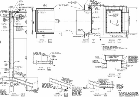
Wastewater Treatment PlantIn 1960 the City of Great Falls constructed a primary treatment plant, located at 1600 6th Street Northeast, which included sedimentation, chlorine disinfection and anaerobic digestion for solids processing. The facility was upgraded and expanded in the mid 1970’s to include secondary biological treatment, solids thickening facilities, and a heat treatment system for solids processing. In 2003 the heat treatment system was replaced by anaerobic digesters. In 2008 co-generation equipment was installed, which utilizes the anaerobic digester gas bi-product for the production of plant electricity as well as thermal energy to heat the digester tanks. In 2011 co-generation saved $151,000 in electricity costs.(See Supporting Documents below for Wastewater Treatment Plant Process)
The City has over 256 miles of gravity sewer collection mains, ranging in age from over 100 years old to newly installed. Pipe materials include concrete, vitrified clay, asbestos cement, brick, cast iron, and in more recent years PVC and HDPE. The current system includes roughly 3,300 manholes and 32 lift stations.

___
Nampa Wastewater Treatment Plant Expansion
Nampa, Idaho
Project Structural Engineer
The Nampa WWTP Digester #3 project consists of the construction of a 1 million
gallon capacity cast-in-place concrete digester, primary digester bldg, generator bldg,
yard piping, electrical, mechanical, plumbing and associated process equipment.

_Ducks Unlimited Gorrill Ranch Fish Ladder
Butte Creek-Chico, California
Butte Creek-Chico, California
- Established
structural design criteria with no site specific geotechnical information
- Designed winter (vertical slot) and summer (horizontal weir) fish ladders
- · Worked closely with the contractor (DB project) to cut costs during construction

_Biloxi Water Well Improvements
Biloxi, Mississippi
Worked with FEMA and the City of Biloxi, MS to rebuild and raise water well platforms and distribution stations following Hurricane Katrina including V-Zone Certifications, BFE’s and RFPE’s
Biloxi, Mississippi
Worked with FEMA and the City of Biloxi, MS to rebuild and raise water well platforms and distribution stations following Hurricane Katrina including V-Zone Certifications, BFE’s and RFPE’s

O'Neal Lane Pump Station
East Baton Rouge, LA, 2013
O’NEAL LANE PUMP STATIONS GROUP B PROJECT
CITY-PARISH PROJECT NO. 10-PS-MS-0051
PROJECT DESCRIPTION: The project consists of constructing 15 pump stations (PS’s 41, 77, 101A (rehab of existing), 139, 149, 153, 162, 175, 189, 191, 224, 227, 326, 345 and 889.) The flows at each are as follows: PS 41 - 528 gpm, PS 77 – 700 gpm, PS 101A – 466 gpm, PS 139 – 306 gpm, PS 149 – 724 gpm, PS 153 – 200 gpm, PS 162 – 884 gpm, PS 175 – 975 gpm, PS 189 – 1084 gpm, PS 191 – 1314 gpm, PS 224
– 1728 gpm, PS 227 – 364 gpm, PS 326 – 385 gpm, PS 345 – 399 gpm, PS 889 – 17,844 gpm. Elevated platforms will be required at PS 41, 77, 101A, 153, 175, 191, 326 and 889. The new PS 889 will replace the existing BPS 889 and will have a divided wet well with 3 pumps in each wet well, with a total capacity of 17,844 gpm and also requires an electrical building.
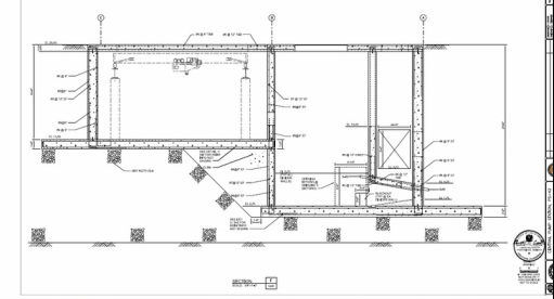
Pump Station 42
East Baton Rouge, Louisiana
This project includes the design and
construction of 40,000 GPM pump
station facility (PS42), vapor phase
biotower-type odor control, and
associated yard piping and valves to
pump the flow from PS1, PS59, and the
LSU pump station to the South WWTP. A new Pump Station 42 will have the capacity to handle 40,000 GPM of peak
wet weather flow and 6,144 GPM of dry weather flow.

SWWTP (South Wastewater Treatment Plant) Wet Weather Improvements Phase 2
East Baton Rouge, Louisiana, 2013
This two-phase project is expanding the existing plant to accommodate 205 million gallons per day (MGD) peak treatment flow and an additional 66 MGD excess flow to equalization storage. Phase I includes modifications to the existing gravity influent pump station to increase its peak capacity to 67 MGD and construction of a new force main raw wastewater and equalization pump station and four new equalization tanks. Phase II includes solids contact basins (pictured below), a blower/electrical building, final settling tanks (FST), FST chemical systems, RSS/WSS pumping, scum pumping and handling, chlorine contact basins, a sodium hypochlorite addition system, an effluent pump station, pipeline and outfall, a 5 MGD nonpotable water pu-mping and distribution system, thickened primary sludge pumping, thickened sludge mixing tanks, control building, and a variety of modifications and site improvements.
Solids Contract Basins, SWWTP, East Baton Rouge, LA
A 22,500 sq-ft reinforced, cast-in-place, concrete structure buried over 24 ft deep supported by over (280 -14 in sq precast, pre-stressed concrete piles.
Administration Building, SWWTP, East Baton Rouge, LA
A two-story, 16,000 sq-ft two story, steel framed office building supported by over (100)-12 in square and 14 in square precast, pre-stressed concrete piles with steel roof trusses.
Laboratory Building, SWWTP, East Baton Rouge, LA
A single-story, 5,000 sq-ft CMU building on a concrete spread footing with steel roof trusses.

Fleming Hill Clearwell Rehabilitation, Vallejo, CA
Rehabilitation of the Fleming Hill Clearwell at the Fleming Hill Water Treatment Plan involved working closely with city officials to repair a cast in place concrete reservoir/clearwell in excess of 50 years old. The project included designing a new under-drain system, significant crack repair and a new concrete lining.
Rehabilitation of the Fleming Hill Clearwell at the Fleming Hill Water Treatment Plan involved working closely with city officials to repair a cast in place concrete reservoir/clearwell in excess of 50 years old. The project included designing a new under-drain system, significant crack repair and a new concrete lining.

6 Million Gallon Reservoir, Roseville, CA, 2002
This project consisted of the design of a circular, 6-MG pre-stressed-concrete reservoir at the City of Rosville’s Water Treatment Plant. Other features of the reservoir included a plant effluent flow control valve, a new storage building, and other minor improvements. water treatment plant. The treatment process consists of coagulation, sedimentation, filtration and disinfection. The pH of the water is also increased to control corrosion in the distribution system and fluoride is added to help prevent tooth decay in consumers. Fluoridation has been a part of the water supply in Roseville since the early 1970’s. Roseville maintains a water distribution system covering the entire city with pipelines ranging in size from four inches to over five feet in diameter. Water samples are collected throughout the system and tested on a weekly basis to ensure quality all the way to each customer. Construction to add an additional six million gallons of treated water storage at the treatment plant site is scheduled to begin in summer 2003. The proposed concrete tank will expand municipal, industrial, irrigation and fire flow storage capacity to serve Roseville’s growing population.
This project consisted of the design of a circular, 6-MG pre-stressed-concrete reservoir at the City of Rosville’s Water Treatment Plant. Other features of the reservoir included a plant effluent flow control valve, a new storage building, and other minor improvements. water treatment plant. The treatment process consists of coagulation, sedimentation, filtration and disinfection. The pH of the water is also increased to control corrosion in the distribution system and fluoride is added to help prevent tooth decay in consumers. Fluoridation has been a part of the water supply in Roseville since the early 1970’s. Roseville maintains a water distribution system covering the entire city with pipelines ranging in size from four inches to over five feet in diameter. Water samples are collected throughout the system and tested on a weekly basis to ensure quality all the way to each customer. Construction to add an additional six million gallons of treated water storage at the treatment plant site is scheduled to begin in summer 2003. The proposed concrete tank will expand municipal, industrial, irrigation and fire flow storage capacity to serve Roseville’s growing population.

5.7 MG Reservoir and Pipeline, Mare Island, Vallejo, 2001
The existing potable water system on Mare Island is serviced by the Vallejo Water District. The system includes a 5.7 million gallon, pre-stressed/post-tensioned, concrete water tank, constructed in 2000, and a gravity-driven distribution system. Potable water is supplied to Mare Island through two transmission mains that cross Mare Island Strait. One main crosses via the Causeway Bridge, and the other crosses via a concrete easement that enters Mare Island just south of Pier 23. Water supply lines extend to the south end of the island and to Pier 35. No potable water supply lines are located at the disposal ponds or at Piers 34 and 35. Potable water supplies stop at the cemetery. The potable water distribution system provides water acceptable for drinking, industrial uses, fire protection, and landscape irrigation. The current system has adequate capacity for existing uses; however, a capital improvement project, primarily for improvements to storage capacity, is planned.
Historically, a saltwater distribution system was used on Mare Island to augment fire protection services and to provide flushing and cooling for ships and submarines at the piers and drydocks. Saltwater also was used for various industrial purposes. The system served most of the industrialized areas of the island, especially the controlled industrial area and the weapons station annex. The saltwater distribution system, though still in place, was abandoned in the late 1990s.
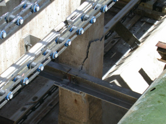
Primary Sedimentation Tanks, NWRF (Northern Water Reclamation Facility), Colorado Springs, CO, 2000
The square, concrete column supporting the scum drive chain and walkway in the Primary Sedimentation Tanks cracked and required repair.
The square, concrete column supporting the scum drive chain and walkway in the Primary Sedimentation Tanks cracked and required repair.
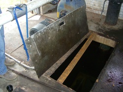
Sanitary Sewage Pumping Station Rehabilitation
Slidell, LA, 2008
This project involved the rehabilitation of a buried, reinforced concrete, sanitary sewage pumping station, a new metal hatch and protective fencing.
Slidell, LA, 2008
This project involved the rehabilitation of a buried, reinforced concrete, sanitary sewage pumping station, a new metal hatch and protective fencing.

Wastewater Treatment Plan Solids Handling Improvements, Great Falls, MT, 2002
The WWTP Expansion for the City of Great Falls, Montana involved the design of several circular anaerobic digesters; a digester control building and the retrofitting of an existing solids process building with a new bridge crane; and a monorail system capable of lifting and moving four centrifuge units weighing approximately four tons each. This project design was done in 3-D, which helped speed the overall design process and provides quantity take-offs for estimating purposes. All new structures for this project were originally slated to be constructed on two-foot-diameter drilled shafts or piers. However, the contractor who was awarded the project expressed a great deal of reluctance regarding the construction of the drilled shafts so alternatives were once again explored (as had been done during pre-design). Eventually, after extensive consultation with the project geotechnical engineer, it was decided that over-excavation (of the expansive clay layer) down to bedrock (in excess of 18 feet) and replacement with structural fill would replace the drilled shafts.
The WWTP Expansion for the City of Great Falls, Montana involved the design of several circular anaerobic digesters; a digester control building and the retrofitting of an existing solids process building with a new bridge crane; and a monorail system capable of lifting and moving four centrifuge units weighing approximately four tons each. This project design was done in 3-D, which helped speed the overall design process and provides quantity take-offs for estimating purposes. All new structures for this project were originally slated to be constructed on two-foot-diameter drilled shafts or piers. However, the contractor who was awarded the project expressed a great deal of reluctance regarding the construction of the drilled shafts so alternatives were once again explored (as had been done during pre-design). Eventually, after extensive consultation with the project geotechnical engineer, it was decided that over-excavation (of the expansive clay layer) down to bedrock (in excess of 18 feet) and replacement with structural fill would replace the drilled shafts.

Cable-supported suspension bridge at pipe crossing, Mather Air Force Base Sacramento, 1999

Flood Control Structures, West Sacramento Flood Control Project, West Sacramento, CA, 1995
Learned the drawing and specification standards of the USACOE, designed a double leaf, steel, mitre gate to span a set of railroad tracks, coordinated work between the USACOE, Caltrans and Union Pacific Railroad.
Learned the drawing and specification standards of the USACOE, designed a double leaf, steel, mitre gate to span a set of railroad tracks, coordinated work between the USACOE, Caltrans and Union Pacific Railroad.
SWWTP Trickling Filter Improvements, East Baton Rouge, LA 2009
The Trickling Filter Improvements project consisted of a 119-mgd pump station design, including a dual-side wet well containing four 600-hp recirculation pumps and six 250-hp effluent pumps, as well as large diameter (40-inch – 84-inch) steel piping. The well construction required a nearly 50-foot-deep excavation in very challenging soils within the Mississippi River escarpment. Piles were initially recommended for both the wet well structure and the electrical building. However, upon careful analysis and cost consideration an alternative foundation type was utilized for the wet well while the electrical building maintained its pile foundation. The new wet well foundation consisted of an expanded mat foundation utilizing adjacent surrounding soils to resist large uplift forces caused by the potentially high groundwater levels. The project is designed to be mechanically and electrically compatible with control modification, which will be required once new wet weather treatment facilities are installed at the plant. These modifications will be accomplished by adjustable weirs and minor programming, and are essentially zero cost.
_
Water Reclamation Facility Upgrade, City of Cape Coral, Cape Coral, FL
The structural design for this $500M program involved water, wastewater, and reclaimed water collection, distribution, storage, and treatment elements. The work included treatment upgrades at the main water reclamation (advanced wastewater treatment) facilities along with planning, design, CM, and start-up of odor control, storage and pumping systems, headworks facilities, and liquid and solids process trains.
Wastewater Treatment Plant Expansion, Central Weber Sewer Improvement District, UT
This work included the structural design for the Central Weber Sewer Improvement District wastewater treatment plant expansion in Northern Utah. The project included the design of a multi-level, CMU chemical building, clarifier, scum vault and concrete containment structure for an air scrubber system. A unique aspect of the chemical building was a rotating ramp mounted on an elevated, exterior platform designed to aid the offloading of chlorine. The ramp could be raised or lowered with the use of a winch mounted on the platform.
Primary Sedimentation Tanks, NWRF, Colorado Springs, CO

